sunnuntai 31. heinäkuuta 2016

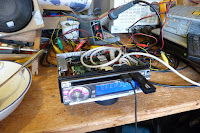
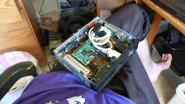
Modding car stereo head unit with Arduino and Raspberry Pi: Part 4: Software: The OPTS

Parts in this series: 1234

THEORETICAL SET-UP:
The Raspberry Pi plays music from a USB memory, reading input from the Arduino Nano.

WHAT ACTUALLY HAPPENS:
The Raspberry Pi does absolutely nothing useful. Software for this does not exist.

So, first, the software running on the Nano is extended to supply key press information and allow showing stuff on the LCD via USB. The protocol is line-based and :-separated; just stuff like ">SHOW_TEXT:Foobar\r\n", "<KEYPRESS:14\r\n".

Then we are left with the mountain of stuff the Pi should do, but doesn't.

What is needed is a media player that supports our custom Arduino-based UI over a USB serial port. It also has to be able to automatically mount and scan USB devices.

Well, I made one. It's called the OVER POWERED TRACK SWITCH.

The main issue was finding a combination of a programming language and a library that would support all media formats with minimal effort, and not crash all the time.

Gstreamer? Maybe. Gstreamer and Python? It's stable, right? Right?

...I tried, it's not. You only have to add time.sleep(1) to the simplest python-gstreamer example and it all comes crashing down with a segmentation fault, no less! And I know, it doesn't even make any sense. I guess you're not supposed to do that, but at the instant I get a segmentation fault from Python, I throw gasoline on my laptop, light it on fire and buy a new one.

So with the (imaginary) new laptop, I removed Python and Gstreamer from my entire world view and stumbled upon libmpv. I tried some Python bindings because I'm stupid, and none of them worked. I wasn't surprised by any amount though, and just started a C++11 project. From there on, everything was relatively straight forward compared to whatever the hell I tried until then.

OVER POWERED TRACK SWITCH
OPTS is designed for this specific use case, but it can also be used in a terminal for testing or as an actual music player if you happen to like the terminal interface.

It organizes all media into albums, which are simply directories on the original media; subdirectories are flattened into the album list after their parent directories. (Or maybe before? I don't remember. Anyway...)

The main user interaction is switching to the next or previous track, or the next or previous album. There are a few repeat and a shuffle modes, a pause function, and a jump-to-random-album function. The current album, track, position, play mode and shuffle order is saved on disk and operation continues automatically when restarted.

OPTS also has a powerful search function that can't be used from the head unit front panel due to the obvious lack of a keyboard, but it is very handy when used in a terminal.

On our Raspberry Pi, we set up OPTS to be run as root as soon as possible at boot as a systemd service. It then mounts, scans and plays any USB media when inserted and... well, then we have a functioning music player.

The software running on the Nano is included in a subdirectory under OPTS, and OPTS is able to check the version and automatically upload a new firmware binary to the Nano.

In addition to that, I created a script that checks the USB media for a specific subdirectory and if it exists, it stops OPTS, copies the new version onto the root file system, builds it and starts it again. This allows me to update OPTS without connecting the Pi into any networks or anything.

I additionally set up OPTS to take input from tty11 and an additional systemd unit to chvt 11 after OPTS has started, so that I can just plug in a USB keyboard and blindly input OPTS commands to eg. search for a track. It's handy.

OPTS is released under the MIT license on Github: https://github.com/celeron55/opts

"This is not the head unit you are looking for"

tiistai 12. heinäkuuta 2016

Modding car stereo head unit with Arduino and Raspberry Pi: Part 3: Connections

Parts in this series: 1234

In this use case, the Raspberry Pi requires at least four connections:
  • A 5V 2A (or so) main power source,
  • USB connection to the Arduino Nano,
  • audio output from the 3.5mm stereo jack, and
  • an external USB connector for playing music from USB mass storage.

Oh... how do you attach it, you ask? I used scrap polyethylene plastic, a small-ish wood saw, very small screws (picked up from disassembled pastic crap) and a small enough drill to add a second "layer" on top of the bottom PCB and attach the Pi and other stuff onto it.

5V Power source

What we have available to us is automotive battery voltage, usually being anything between 11 to 15 volts, sometimes down to 0 volts, and sometimes up to basically anything, in the case of eg. a loose alternator connector or whatnot. Basically, this is able to kill our device in rare circumstances unless our device has protection circuitry to tolerate something like 230VAC.

Well, I'm lazy, but not stupid. I happen to have a couple of cheap DC-DC switch mode power supplies from ebay that handle up to 60V input, 3A output and can be configured to put out 5 volts. One of these will be fine enough here - if it breaks, it breaks, and if it breaks our Raspberry Pi, 100€ lost at tops.

Now, the Nano has to be able to switch this power on and off. It can be done by desoldering and lifting up the ON/OFF leg of the LM2596HV regulator IC and applying 0 or 5 volts from the Nano...

...except that if we did that, the Pi+Nano combination would end up in an infinite restart loop, because the Nano always restarts when the USB device is opened in Linux, causing an undefined state on the ON/OFF pin while the Nano is booting up.

What we can do is add a capacitor from the ON/OFF pin to ground, and add a resistor in series with the control wire coming from the Nano. This way the ON/OFF pin state will stay the same long enough while the Nano restarts when our software running in Linux is opening the USB virtual serial port in order to talk to the Nano.

Now just add a lot of insulation tape and cram that switch mode power supply somewhere inside the head unit...

USB connection to Arduino Nano

This is just a shortened USB cable. Nothing to see here. Use heat-shrink tubing for insulation so that you'll never have to come back to it.

Audio output from the 3.5mm stereo jack

There are a few places on the head unit PCB we could insert this signal into, but the one that makes the most sense is the CD-ROM drive signal lines; their input side is completely disconnected as the CD-ROM module was removed, and the wires coming from the 3.5mm stereo jack can be soldered directly onto those signals. The signal voltage levels are probably close enough.

New layer of plastic on top of the PCB and the audio input cable hanging from the PCB.

An external USB connector

This is more of a mechanical thing. You need a short USB A male-female cable, a file, a sharp knife, some spare pieces of plastic or wood or something, a drill, screws, some zip ties and super glue and whatever you are comfortable with to attach the female end to poke through the front panel enough to hold a USB dongle.

You probably also want an external RJ45 ethernet connector for connecting using SSH for debugging and moving files around and whatnot. It just adds to the physical torture. A female-to-female adapter and a very short cable is handy.

Building a solid base from plastic for super gluing and zip-tieing the USB female connector onto, very finely positioned to poke out from the original CD-ROM slot.
The CD-ROM slot was modified to house the female USB A connector using a knife and a file. The front panel still comes off as originally designed.
Next: Part 4

sunnuntai 10. heinäkuuta 2016

Modding car stereo head unit with Arduino and Raspberry Pi: Part 2

Parts in this series: 1234

Now that the Arduino (Nano 3.0) is able to control everything that we need, I wrote some software on it.

I think I'll publish the source code later, but here's what the connections ended up being:

const int PIN_LED = 13;
const int PIN_MAIN_POWER_CONTROL = 4;
const int PIN_LCD_CE = 7; // <- LC75854E
const int PIN_LCD_CL = 8;
const int PIN_LCD_DI = 9;
const int PIN_LCD_DO = 10;
const int PIN_ENCODER1 = A0; // <- The digital potentiometer
const int PIN_ENCODER2 = A1;
const int PIN_VOL_CE = 11; <- LC75421M
const int PIN_VOL_DI = 12;
const int PIN_VOL_CL = 13;
const int PIN_STANDBY_DISABLE = 5;
const int PIN_RASPBERRY_POWER_OFF = 2;
const int PIN_IGNITION_INPUT = A2;


MAIN_POWER_CONTROL powers up the volume controller and LCD backlight. These controls were originally 5V, so they can be just wired directly to the Nano. It goes through some resistors and transistors which turn on the beefier regulators on the original circuit.

STANDBY_DISABLE disables the TA8272H power amplifier standby mode (that is, it just goes to the STBY pin).

IGNITION_INPUT senses the incoming "ignition" signal which is controlled by the ignition key, so that things can be automatically turned on and off with the rest of the car.

The Nano is fed constant power from battery voltage, and is never switched off (*). It has three modes: POWER OFF, AUX and RASPBERRY. The modes are cycled by pressing the power button, which is queried from the LCD controller which also stays powered in all modes - just like it originally does; it uses a fraction of 1mA even in full operation. When in POWER OFF mode, the Nano switches everything off, and in other modes it switches everything on.

(*) This results in a shutdown power consumption of like 20 to 30mA, which will drain the main battery in a couple of weeks. It's fine enough for now, but in the long term I should probably remove the power LED from it and use the maximum clock divider when in POWER OFF mode; this should result in just a few mA for the AVR. What would then remain is the Nano's CH341 USB serial chip which is always powered on and probably takes something like 5 or 20mA. Not sure. In any case, it might be possible to cut some of the PCB traces to it to make it only powered when USB power is present. This might be a future subject.

...

What now? Well, we have to be able to control this thing somehow.

And actually not just somehow; I want a better user interface than is commercially available in this price range. Take a look at the front panel here:


Now, here, importantly, the previous functions of the buttons are completely irrelevant. We can do *anything*, and I have specific preferences when it comes to this:
  • The knob must control volume in the default state in all modes
  • Pressing the knob must be always related to whatever turning the knob does
  • Track switching must be allocated to large buttons
  • Album switching must be allocated to large buttons

It is wise to split the controls statically into two parts, one of which will control the Nano, and the other part will control the Raspberry Pi.

As the Nano will control of the volume, we allocate the digital potentiometer to it, and also the button that is pressed by pressing the knob. And that's it; nothing else is needed except the knob and the power button. There will be an options menu that comes up with a long press of the knob for bass, treble and some other special options.

After writing more software, what exists at this point can be described as an Arduino controlled car stereo that is able to power on and off, select the AUX input and has working volume control. It's cool, but just a subset of what the original MCU did. You can show custom texts on the LCD though, which is fun:


The rest of the buttons will be mapped in software running on the Raspberry Pi, but I already noted that there isn't much doubt that the best mapping will be to switch tracks using the original up-down track switch lever, and switch albums using the huge buttons above and below it.

Before that can happen, the Pi has to be wired in somehow.

Next: Part 3

lauantai 9. heinäkuuta 2016

Modding car stereo head unit with Arduino and Raspberry Pi: Part 1

Parts in this series: 1234

AN OVERPOWERED SOLUTION TO A BARELY EXISTING PROBLEM!

First you need a 2000s car stereo head unit like this AIWA/Sony CDC-R237 from 2003. It's barely useful as-is because it doesn't even support MP3 CDs.


Let me tell you, these units have some interesting properties. Or at least this one does:

It sounds quite nice. I wouldn't call it hi-fi, but it isn't afraid of any frequencies and it very nicely avoids sounding too "sharp" or "digital"; I like it. It works very well for the kind of funky space dance videogame remix stuff that I listen to. It will turn out all of what makes that sound can be re-used.

The large front panel buttons are implemented by individual switches with a very snappy feel, which I, frankly, require; I can't stand the rubbery crap they use on cheap units. The front panel display contains 8 14-segment characters, a 9-segment progress bar and a bunch of miscellaneous symbols. I consider something like this to be the best user interface that a car music player can have. Maximum clarity and minimal distraction.

So, let's open it!


The optical drive is a module that can be removed by removing a few screws and one cable. It consumes most of the space inside the unit but contains nothing else than what is needed for reading the disc and putting out a line-level stereo audio signal. It is controlled by the main microcontroller by a serial protocol of some kind. It can be just picked out and everything else still works. So, we do that. (Beware: units that support MP3 CDs probably differ from this.)


The removable front panel contains an LC75854E LCD controller and it is almost entirely controlled by the serial protocol of this IC. The datasheet from 1999 is readily available. We will certainly make use of that. The digital potentiometer, eject button, AUX input and operating voltages are wired separately.


So, what's putting out the sound to the speakers? What we have here is a very common construction in car stereo head units: It's just an integrated four channel power amplifier IC - this time from Toshiba - a TA8272H.

The inputs to this power amplifier can be traced out to a weird muting circuit implemented with discrete transistors, and then we find out that they come from this IC, marked LC75421. The datasheet is available, and tells us that this is a volume controller chip controlled by a serial protocol. Like the LCD controller, we can just carefully read the protocol spec and control the thing. In addition to just controlling volume, it supports input selection from 5 stereo sources, it has bass, treble, balance and fader controls, a bunch of other stuff and outputs 4 channels as required by car stereo systems.


So, it's all fun, games and serial protocols!

Well, not really. Tracing out things on the PCB is generally not fun. The power management circuitry on this thing is practically impossible to fully understand and I had to take some shortcuts to get it all powered up. Also, working with these kinds of single-sided PCBs with no plated holes is a pain in the butt because the copper tends to peel off, and consequently snap off.

Regardless, eventually I managed to find enough spots to inject control signals into to get it all powered up.

The way this works from the factory is that the main MCU is always fed 5V power, and there's a whole bunch of signals coming out from it. For example, it appears there is a separate control signal for the MUTE and STANDBY inputs of the power amplifier, and in addition to those there's this weird discrete mute circuitry - and some of those require an another section of the PCB to be powered up, by yet another control signal. It creates quite the puzzle.

Basically, once you've spent an hour and gotten nowhere, you just solder a wire onto the base of a transistor and get on with it. Make sure to leave one of the mute circuits functional though; you don't want the pops and cracks that otherwise happen when things switch on and off.


So, now we have a head unit in which the original MCU is cut off from everything and instead an Arduino Nano manages the power and controls the LCD, the buttons and the volume controller.

Continued here: Part 2

torstai 14. huhtikuuta 2016

Säätö #5: Laite joka lausuu kellonajan nappia painettaessa


Paina nappia, ja kaiuttimesta kuuluu kellonaika. Omituisuudet:
  • Hieno arduino-konepuhe josta ei saa 50% ajasta selvää (https://github.com/jscrane/TTS)
  • Kellonaika asetetaan kytkemällä usb koneeseen ja avaamalla sarjaterminaali
  • Paristot kestää arviolta n. sata vuotta kun ne syöttää arduinoa vain napin ollessa pohjassa; muulloin pelkästään RTC-piiriä
  • Kaiuttimelle menee jotain pwm:ää arduinosta jollain randomilla vastus-konkka-kela-konkka-suodatuksella

lauantai 6. syyskuuta 2014

Säätö #4


Söpö pieni johtosarja:


Prossulevyn aloittelu:


SERVICE POSITION!

5/5 modulaarinen rakenne:


Diagnostiikkastriimi bluetooth-sarjalinkin yli jolla voi myös ohjelmoida MCU:n. Jebin!

Videoita robottiprojektista julkaistaan täällä: https://www.youtube.com/user/celeron55/videos

perjantai 5. syyskuuta 2014

Säätö #3

Olen viime aikoina väsäillyt moottorinohjaimia sängyn alla ja pöydällä neljä vuotta elektroniikanpuutteessa lojuneeseen taistelurobottiin.


^--- Tässä ensimmäisessä kuvassa näkyy myös pikaisesti väsätty 0...800kHz PWM-generaattori. Siinä on lähinnä attiny25 ja pari potikkaa, tässä softa: http://fpaste.org/131175/05396140/

Itse pääsyyllisessä on kahden fetin puolisilta, isoloiva fettiohjain, PWM:stä deadtimen kera ohjaukset tekevät pari quad-nand-porttia ja virranmittauspiiri. Suunniteltu 3 minuutin käytölle 100A@25V:llä tuohon koteloon lämpöä johtamalla.